Wind Tunnel
This Research Guideline gathers those projects developed in the Wind Tunnel. This facility is provided with a test room to obtain a rectilinear uniform flow of air with constant speed.
Inside Wind Tunnel’s test room, real scaled objects and models are located to observe the real effect of the wind over them, so that it can be studied.
The test room is modular and can be dismantled, so that it can be adapted to each test’s requirement. The innovations in its construction, power plant and control, make the tunnel extremely competitive in terms of costs and features as well as suitable for a wide range of applications, such us:
- Civil Engineering
- Architecture
- Renewable Energies
- Sports Training
- Agricultural R+D
The outstanding features of the aerodynamic tunnel for Civil Tests are:
- Closed circuit.
- Test room: 2x2 m2 of section and 3m long
- Maximum speed of operation: 56 m/s
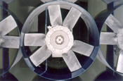
- Nine fans of 22 kW each one, controlled by a frequency converter.
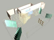
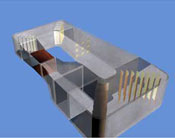
Tunel Map

- 1.Tunnel Map
- 1. Fan Installation
- 2. Diffusers
- 3. Corners (Vanes)
- 4. Settling Chamber
- 5. Nozzle
- 6. Test Section
- 7. Control room
Technical description
Aerodynamic Tunnel for Civil Tests of ITER is the first wind tunnel in the Canary Islands. It has been designed specifically for the realization of civil rather than aeronautical tests, increasing its efficiency and versatility meaning a great advance in many fields of aerodynamic research.
Aerodynamic tunnel is a key tool to study air or wind effects over any object (an aircraft, a structure or earth surface itself). It makes air flows with the required features and an acceptable quality level, so that tests can be done by making this air draught come into contact real objects, if their size makes it possible, or with scale models. Results can be extrapolated from this, due to the dynamic laws.
This way, predictions can be made of the real effect winds have over objects, being able to reduce them or design and evaluate solutions, if necessary.
The tunnel has a closed circuit and one closed-test room, which means less power consumption, reduction of acoustic pollution, and better flux quality in the test section. Confining the working fluid, closed-circuit tunnels makes easy the use of visualization techniques with smoke, particles, etc.
The power plant is composed of 9 fans, each one of 22 kW which each produce 24m3/s. The speed of these fans is regulated by a frequency inverter, and a maximum speed of 56 m/s (200 km/h) is reached in the test section. The dimensions of this section are 2x2 m and 3m long, and it has a plate glass security window, so the tests can be perfectly observed from the control room. Moreover, the test section has been built in a modular and exchangeable manner, so that it can be perfectly adapted for the requirements of each and every test.
The contraction reduces the section gradually, from the maximum of the return-circuit to the maximum of the Test Room, accelerating the air draught till the required speed and fulfilling important functions for the flow-quality, such as diminishing turbulence, improving velocity distribution uniformity and linearity of flow. Diffusers reduce air speed once it has gone through the Test room in order to minimize charge-loss in the Return circuit and, therefore, the required power of operation in the tunnel.
Due to the fact that this wind tunnel is a closed circuit type, it is necessary to force the flow of air to turn around the corners of the circuit. To avoid large losses, and to maintain relatively straight flow throughout the circuit, the corners are equipped with turning vanes. These corners are not as aerodynamic as they should due to their high costs.
Instrumentation
Aerodynamic Tunnel for Civil Tests has a wide variety of instrumentation.
The Wind Tunnel for Civil Tests has a complete instrumentation. The speed of the fans is regulated with a frequency inverter of 220 kW, so the airflow speed can be efficiently controlled, obtaining the required wind speed in the test section. This system is located in a room beneath the tunnel and it can be operated either manually or remotely from the control room.
A “Scanivale” 48-channel device is used in order to measure the pressure and wind speed on models. The pressure transducer signal amplifier is connected to a computer in the control room where data is filtered and stored using ITER developed software that also allows real time plotting for each channel.
Air flow speed is measured and controlled with several static-Pitot tubes, as well as with a hot wire anemometer, in the Test Section.
In calibration tests in the tunnel, a pressure comb has been used, that is also useful in other kind of tests. It is also provided with a camera to record tests.
During start off phase and tests, a visualization system with threads, has been successfully used, whether to see the flow on scale models or to show that the flow is laminar before and after the contraction.
Soon, it is planned to install a bascule of six components to measure global aerodynamical forces, appropriate for heavy models up to 1000N and integrated in the control system of the tunnel. The tunnel will also have a smoke generator in the future. Although the visualization with smoke is not strictly necessary, it is sometimes recommended, especially for its didactic possibilities.
Applications
The innovations introduced in this tunnel during its construction as well as in the propulsion and regulation systems, make it high competitive in costs and services. It has been conceived for civil applications, so it does not have to fulfil aeronautics requirements that would entails higher installations and working costs.
The applications of this tunnel are the following:
CIVIL ENGINEERING
Wide range of tests can be developed in this area, therefore, only the most outstanding ones will be detailed. Among them, it's remarkable the determination of static and dynamic wind loads over bridges and other civil structures, such as industrial units, bus shelters, etc. These loads can be very important when the structure is calculated, because loads inferred from norms might not be right when looking for a more adjusted design.
Another kind of research is the determination of wind load on land vehicles and the study of road devices to reduce them. Both studies are very important to improve security in roads, because as it's well known, wind over bridges or in ravines after a cut causes lots of car crashes.
A similar case is the study of wind effect inside docks, airports, etc. For example, a real case example happened in Holland, where the bad location of one hangar produced bad wind gusts above the runway of the airport of Amsterdam. This can be absolutely avoided by testing the designs before in an aerodynamic tunnel, assuring that models are viable and suitable, and avoiding the future modifications in the original model with the considerable costs increase of that this represents.
Finally, and although there are more applications in Civil Engineering, there are studies about solid and liquid pollutants spreading. In this case, scale model tests can be very helpful for environmental impact studies.
ARCHITECTURE
Tests in this field can follow two different ways and can be performed in the aerodynamic tunnel s. On one hand, they are designed to calculate wind loads and on the other hand to the research on bioclimatic models.
Due to the lightness of modern architecture structures, an exhaustive knowledge of loads is required. Therefore the measure of wind loads over buildings and other architectonic elements (roofs, fences, sculptures, etc) in the tunnel would help to minimize the needed structure.
It is also important to determine local effects of wind over certain buildings and to study possible solutions when problems appear. Buildings on windy areas can show local wind load problems that can make their coating fall partially or produce whistling or excessive wind flows affecting to the dwelling’s comfort.
Besides, it's indispensable to characterize wind effects in open areas, building entrances, etc and evaluating the wind barriers helps to solve local wind problems. In this case, the matter is to find the best building orientation so that wind effects can be minimized in its entrance and in its recreation areas, or to design natural or artificial barriers in order to minimize wind effects in certain areas.
Finally, referring to bioclimatic techniques, researches can be done to evaluate natural systems of ventilation, which is a very important way to reduce maintenance costs in dwellings, due to the energetic saving that it involves.
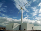
RENEWABLE ENERGIES
Regarding to the Renewable Energies, the tunnel can be used to develop wind turbine components, to study loads over them, and to calibrate anemometers.
It is also useful to study shadows in Wind Farms and to determine the best location for turbines in Wind Farms, depending on the local winds or terrain shapes so that an optimal distribution in the least amount of land can be achieved, is also an important task in this area.
On the other hand, research on Photovoltaic Energy field is specially focused to decrease costs by means of concentration systems. The monitoring structure of the photovoltaic parabolic concentrator shows many differences with the structure of plain panel. In concentration systems, structures must support big loads without suffering damages (break or permanent deformation) and must ensure that deformation levels suffered by the structure are compatible with "linen up" optical devices and receivers under typical loads, as well. These requirements makes these concentration structures very big nowadays, not only because of the weight they must support, but mainly because of the wind loads conditions they work under, that falls directly in its costs.
Tests in the aerodynamic tunnel are required in order to design and study other choices to make the tracking structure, so that the forces it is put under, due to wind, are as low as possible, becoming lighter and cheaper structures.
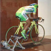
SPORT TRAINING
Sport efficiency improvement strongly depends on the capacity to minimize aerodynamic resistance. This fact is very important for several sports, such as "ball sports" or different athletics specialities, cycling, ski, etc.
The best way to know and minimize this resistance is performing tests in the aerodynamic tunnel. This test allows simulating almost every parameter that affects in sport practice, so that it makes the tunnel a very efficient instrument to improve this.
AGRICULTURAL R+D
On one hand, researches on this field are related with the design and evaluation of barriers against wind, mainly studies about its application for estates in windy areas or with a special orography, that requires a detailed study, as well as specific studies in areas affected by wind.
On the other hand, there are researches for the determination of loads on the top of agricultural warehouses or greenhouses. This kind of application is very interesting in the Canary Islands, because, as it is well known, a little change in the orientation of covers means a big reduction of wind loads.
Services
Study in the Wind Tunnel of the extension of Güimar´s Industrial Estate´s impact over the sand of wind contribution placed in Güimar´s Malpaís.
The aim of this Project was to analyze the effect of the extension of Güímar´s Industrial Estate towards the southern section of its actual location over the sand of wind contribution placed in the Special Natural Reservoir of Guimar´s Malpaís.
It is known that the particles of sand follow the direction of the flow lines that come from the beach, therefore the best way to carry out the study, Is to focus in the alteration produced by the wind flows in the temporary buildings of the industrial estate.
To predict whether the sand in the inside of the Malpaís will be affected, several tests were carried out with the actual configuration of the area, including the area that will be added to the industrial estate. After this, the same tests were carried out, but this time in the dwellings and the predictable buildings of the estate, comparing later both results and establishing the planned action effect in the sand strip.
Several types of tests were done: visualization, with which is possible to detect the alterations produced over the flow lines, and quantitative tests, measuring the forecasting field of pressure in the target area, that allow to the verify the variations produced in the speed module.
Biomechanical Study of the aerodynamic resistance of professional cyclists of the G.D. KELME in the Wind Tunnel
Five runners of the cyclist professional team KELME has carried out tests in the Aerodynamic tunnel for ITER´s Civil Tests, being the first Spanish team that chooses this practice. During the tests, which were carried out at constant speed in the anaerobic verge of the cyclists, at 54km/h, their aerodynamic resistance was measured along with the developed power throughout the training, with the goal of optimizing their performance through aerodynamic improvements.
Aerodynamic Sensibility test for the assembly conditions of anemometers.
The aim of these tests was to verify how the inclination to the horizontal plane of a cup anemometer affects to the measures undertaken. Firstly the characterization of the exact place where the anemometer and its support would be placed in the test room of the wind tunnel is done. Subsequently, the studied anemometer is calibrated following the MEASNET" Cup Anemometer Calibration Procedure" and then the calibrations are repeated changing the angle between -4º and 4º.
Anemometer Calibration
The calibration of anemometers from different suppliers is one of the services that take place in the Wind Tunnel. (See facilities).
To carry out calibrations, the MEASNET" Cup Anemometer Calibration Procedure" is followed. The 2.0 x 2.0 m section of the test section, allows that two anemometers get calibrated at the same time, this being an advantage over other wind tunnels. As a previous step, the two points of the test section (where the anemometers will be placed) were characterized with precision by means of one Pitot tube and a hot wire anemometer with calibration certification. These two points are in the middle section of the test chamber, which was perfectly characterized by a total pressure sensor array.
Inside the test section, the blockage effect is very small, because frontal surfaces of anemometers with its stands are less than 3% of the test chamber section surface (2.0x2.0m), instead of the 5% limit fixed by MEASNET. However, in order to reduce this effect, the calibration of the two areas has been made removing the anemometers cups and using their stands to fasten the measure probe. The blockage made just by the cups is about 0.15%, so it can be ignored.
The calibration procedure begins sampling the initial conditions; these will be used as a reference to adjust the following samplings. Afterwards, the anemometer shall run in for about 5 minutes at 5 m/s in order to avoid the effect that large temperature variations may have on the mechanical friction of the anemometer bearings. Calibration shall be performed under both rising and falling wind speed in the range of 4 to 16 m/sec at a calibration interval of 1m/s or less. By taking readings both for increasing steps and for decreasing steps, it is possible to identify whether hysteresis effects are present in the measuring equipment. Sampling frequency is 60 Hz, and the data acquisition takes place during 30 seconds. The test finishes with the final condition sampling.
The instruments used to calibrate were the following: differential pressure sensor, temperature sensor, A/D converter, frequency meter, barometer and a higrometer.
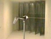
Features and performance of low power wind turbine analysis
The power curves of three wind turbines were obtained in the wind tunnel: Spiral Wing SF1, DF1600 Station and Air 403. Using the tests in the wind tunnel, the power curves of the above-mentioned wind turbines were calculated. This curve shows how much power can be produced for any wind speed.
This is the best way to calculate the curve, because the tunnel permits high quality and stable air flow at a determined speed for enough time to make the required measures. Besides, an accurate wind speed measurement can be done at all times, as well as start-up and cut-out speed measurements.
The three wind turbines tested are low power ones, and because of their sizes, the real models where placed in test room and no scale model was needed.
Wind turbines are connected to battery series, in order to test them in real operative conditions. Voltage and current are measured simultaneously to obtain the generated power. The main goal is to measure the output power of the wind turbines after all inner losses. This way, it is possible to measure only the power supplied to load.
Projects:
Minieuclides: design and development of a prototype of a photovoltaic concentrator.
The object of this Project has been the implementation of a photovoltaic concentrator prototype with a full - load rating grid connected system of a 5 kW of power.
The dimensioning of the support structure and of the tracking system of the concentrators designed prototype was conditioned mainly by the aerodynamic loads that generate forces approximated to the weight of the structure. In or case, focused to obtain a lighter structure but with enough rigidness to support the loads to which it will be exposed, is absolutely necessary to accurately know the aerodynamic loads, which is only possible with the tests in the aerodynamic tunnel with the designed configuration. The tests carried out were directed to measure the two types of deformations that the structure could suffer due to the wind loads, flexion and torsion, and those responsible for the optical disalignment, with the aim of determining if the structure is rigid enough to support the wind loads, or if on the contrary, we have chosen structural requirements above the necessary. Experimental developments of this type of tests normally consist in the measurement of pressure, force and momentum data. Obviously, the forces and momentums are necessary from the cementation and structurals design point of view. Pressure data is necessary to limit local deviations of the reflector in itself, this is, to prevent the optical disalignment taking into account that the structures turning angle goes from 180º to +180º.
The tests were carried out at different speeds, basing them in historic wind data measured in the meteorological station of EUCLIDES plant.
In order to take these measurements, the concentrator model was fixed to the scales platform by a support designed especially for that purpose. To complete the tests, these were done varying the orientation of the optical system of the structure; just at it does for real. This way, variations in the exerted load of the wind can be obtained, depending on the position of the structure, exterminating which positions are those with the greatest and the least resistance.
ELT: Extremely Large Telescope Design Study
The ELT is a project financed by the VI Frame Program, PROFIT and coordinated by the European Southern Observatory, ESO. The work package, in which ITER participates, The Wind Studies, is also made up by the International Centre of Numeric Methods in Engineering (CIMNE), the European Southern Observatory (ESO) and the Astrophysics Institute of the Canary Islands (IAC).
The ELT design Study is a technologic development program carried out by institutes and companies in Europe, Israel, and Australia, coordinated by ESO (European Southern Observatory). It is approximately one third co-financed by of the VI Framework Program. The Wind Studies also count with a loan of the Science and Education Ministry inside the PROFIT program.
The study covers the development of technology and concepts needed for the design and eventual construction of an Extremely Large European Telescope. ITER participates in this project in the Work Package of the Wind Studies. It is in charge of the manufacturing of scale models of the selected enclosures installed with pressure measuring sensors and the accomplishment of tests in the ITER´s Aerodynamic Wind Tunnel, previous to those that will be carried out in a boundary layer wind tunnel.